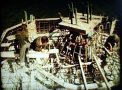
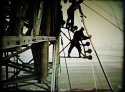
We start with the construction of a crossing tower. Bolt assemblies are fixed at each corner (to form the bottom of each leg).
|
Parts are assembled on the ground and lifted with a 125 foot derrick (crane).
|
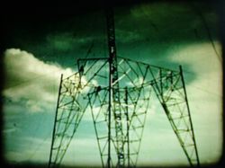
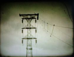
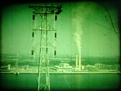
Slowly the tower takes shape.
|
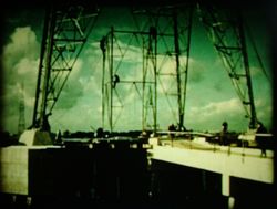
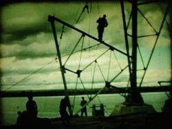
Once the main body is done, a centre column 15ft square is built.
Because the tower has such a wide base, it's easier to get a straight
lift inside the tower.
|
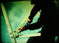
Bolts are tightened by hand.
|
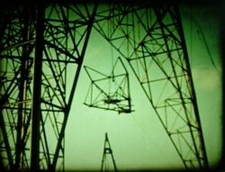
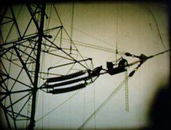
The cross arms are lifted up the tower, one at a time. Each weighs 2.5 tons
and will support a 3 ton insulator set.
|
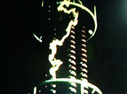
In the lab, the insulators are given a flashover test at more than 1,000,000
volts. Once on site, they are winched up the tower, completing the pylon's
construction.
|
The conductors (wires) must be strung through the pylons without touching
land or water at any point, to avoid damage from abrasion.
|
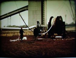
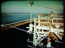
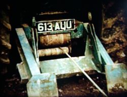
In order to keep the conductors off the ground, they will be
pulled across using ropes. These ropes are laid on the
river bed and then pulled taut by winches.
|
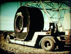
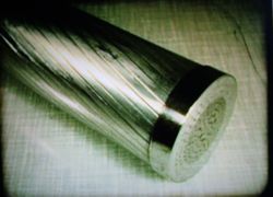
The conductors arrive in reels, ready to be connected to the ropes and
hauled up onto the pylons.
|
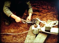
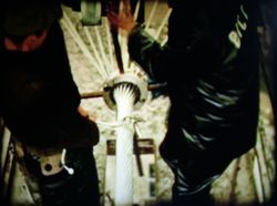
A pulling plate is attached to the end of the conductor...
|
...then it is attached to the haulage rope and begins rising
towards the first anchor tower.
|
As the conductor approaches the tower it goes over rollers...
|
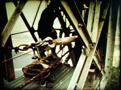
...through a cradle attached to the side of the tower.
|
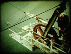
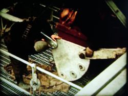
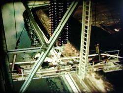
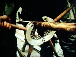
As the conductor passes through the anchor tower, every
80 feet of the track rope a trolley is put on,
which is clamped to the haulage rope.
|
To each trolley a boom is attached, with a bobbin...
|
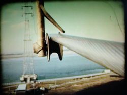
...which supports the conductor as it continues towards the crossing
tower.
|
The conductor passes through the crossing tower's cradle and is now pulled
across the river.
|
As each suspender reaches the crossing tower, it is removed
and reattached on the other side.
|
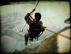
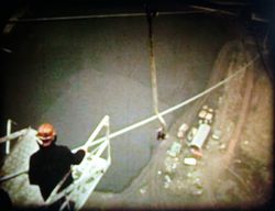
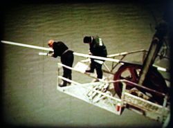
Once the conductor has reached the opposite tower,
an engineer checks the ropes and wires.
|
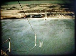
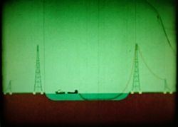
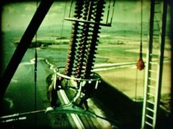
As planned, the conductor now crosses the Forth,
hanging from the ropes on suspenders.
|
Back at the start point, the end of the conductor passes into the first
anchor tower, where it is attached to a quadrant plate.
|
This way, the trailing end of the conductor is supported clear of
the tower.
|
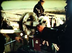
Now both ends of the conductors are attached to winches, which
start turning.
|
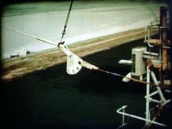
As the winches pull the conductor tight, it lifts up,
pulling itself free from the suspenders. Above, you
can also see the cradle on the side of the tower.
|
Now the cradle is lowered until the conductor it supports is
at the right height for attaching to the insulator set.
|
The ends of each conductor are attached to the tension
insulator sets on each anchor tower.
|
On the crossing towers, where the conductor will be connected to
suspension insulators, a layer of armour rods are attached.
|
This will prevent damage to the surface of the conductor,
which is then attached to the bottom of the insulator set.
|
Dampers are added to the conductor to prevent the wind
causing dangerous oscillations.
|
Finally, arcing rings are fitted to the insulator sets.
|
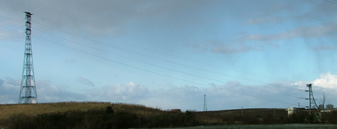
That's it! All six conductors, plus the earth wire at the
top, are strung by the same method. Finally the track and
haulage ropes are removed.
|